| - MRR TUTORIALS - CONTROL - ANALOG AC |
Märklins Analogue AC system
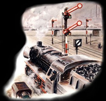
100% European nostalgics!
| RELATED DOCUMENTATION ABOUT AC-CONTROLLED LAYOUTS: | |||
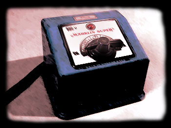
| The blue Märklin transformer hums pleasantly to the ground as the plug is inserted. A gentle turn on that steering wheel and train set begins to roll forward. The steering wheel does a bit of raspy resistance as the towing contact on the inside moves over the windings of the transformer. The lamps shine as it passes through the first tunnel. Gears are switched on the blue switchgear and the train arrives at the station shortly. A familiar scent of model trains spreads throughout the room. The transformer rating plate has already become lukewarm. | Different types of operator panels |
Märklin Signals 7000-series Hand book |
|
Advantages of analogue AC operation
- Easy and understandable to connect the electrical system. Some cables in different colors are all needed.
-Transformer, relays, flip-flops and buttons give so much more feel than touch screens and computers. Model rail is at its best with real tram boards and transformers.
- Lowest price. Once you have purchased your entire facility with locomotive wagons, tracks, transformers and everything you ever wanted, it has cost no more than a mock stealer compared to the tricky digital stuff.
Disadvantages of analogue AC operation
- Highly restrictive in multi-train traffic.
- Significantly much more wiring than digital operation.
- Significantly poorer driving characteristics of the locomotive and no access to the built-in sound effects.
- Extremely restrictive for automatic traffic and combined control of signals and switches..
How to power your analogue AC power supply
Simple! Only two wires involved!
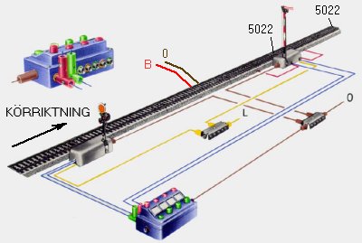
Märklins electrical system for operation with AC (AC) consists of two components; a torque transformer and a current rail. The power strip has two connected wires; one brown and one red, which are connected directly to the color-labeled terminals (brown and red) on the transformer. Brown is electric zero and is often marked with "0". Red is electric phase and marked with "B".
The transformer The voltage in the red-labeled socket (also labeled "B") can be adjusted from 0 Volt position (max counterclockwise) to 16 volts (max clockwise) with the knob / knob. To change the direction of travel, a voltage shock of about 24 volts is given (resilient position max counterclockwise, or by pressing the knob / knob). The yellow marked socket "L" provides 16 volts at all times. This socket is used for operation of signals, electrical magnetic articles (eg switches and relaxation rails), as well as possible lighting in houses and on platforms, yards etc.
|
 |
|||
The power supply track section
|
|
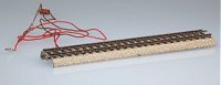
It is therefore very easy to make more power supply rails yourself. All that is needed is cable, tin and a soldering iron. In addition, some track sections have a small capacitor connected. It is not necessary and can be omitted. The purpose of the capacitor is to reduce the electrical interference caused by the locomotive when traveling on the rails. In the event of a later transition to digital operation of the train, these capacitors must be removed and then it is nice to have already removed them from the beginning and thus not have to tear up the rail at their layout. |
|
|
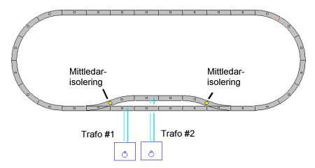
Multi-train traffic with transformer operation (Analog operation) Insulation between sections |
Connection of current to each new section Polarity check
|
 |
|||
I have connected all my transformers to one branch outlet. When I am going to drive that I simply put in the power outlet and then I know that all transformers are properly connected each time (because I never pull them out separately).
|
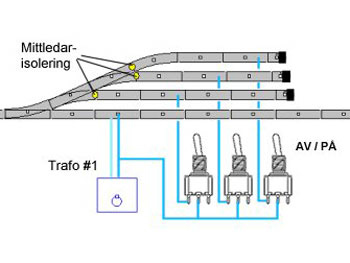 |
Fiddle- and staging yards This is most easily done with the help of a toggle switch. How this is conected is shown in the picture here. The toggle switches are mounted in a control panel next to the transformers so you can easily reach them. / Martin |
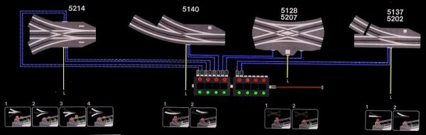
How to wire Marklin turouts
Remote control is next level !
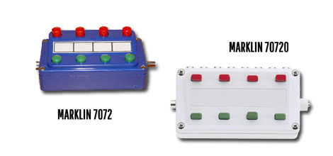
The Märklin series 5100/5200 metal rail includes a number of turnouts that can be operated remotely. Remote maneuvering is done using Märklin's switch box item 7072, or rather with toggle switches mounted in a home-built control panel. The Märklin electric turnouts have built-in solenoids that moves the turnout tongue. A solenoid is an electromagnet with a moving iron core.
The solenoid has three connections:
- Yellow cable that connects directly to the transformer yellow socket marked (L).
- Blue cable with red contact is connected to the red terminal of the switch box 7072.
- Blue cable with green contact is connected to the green terminal of the switch box 7072.
|
The lamp is connected to the rails (0) This is important to know in the event of a later transition to digital trains. Namely, it is the only electrical connection between the digital drive voltage and the AC transformer.
|
|
 |
3-way turnout (Article 5214) Two of the blue cables are interconnected to provide straight track maneuvering. The other two give right, and left turn respectively. Maneuver from left turn to right turn and vice versa, must be done via straight ahead, for the groove tongues to end up right.
/ Martin |
Märklin Signal system 7000
A good start to get started on automatic train traffic
Unfortunately, I have always known that Märklin's signal system 7000 has been difficult to connect and use. It's a shame, since I now far in hindsight realized that I really could have had great benefit and pleasure from some signals on my first three layouts.
All at a cost of a few hundred pieces and with only a few simple handles for installation. That is why I am now writing this guide For those of you who build a larger layout, more than 20 turnouts and simultaneous operation of more than 4 locomotives, I recommend instead to invest directly in digital system with PC control. Three types of signals in series 7000
|
 |
|||
|
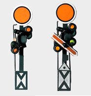
Pre-signals on the model railway The pre-signals in Märklin's signal system 7000 have article numbers:
|
|
|
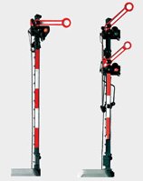
Main signals on the model railway The main signals in Märklin's signal system 7000 have article numbers:
|
|
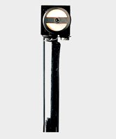
The track interlock signals in Märklin's signal system 7000 have part numbers:
|
|||
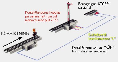
Connect the Märklin's signal system 7000 The signals have 3 blue cables, one with red contact, one with green and one with orange contact. By briefly connecting the red or green signal of the signal to transformer "0", the signal is set to "STOP" and "RUN" respectively.
|
Then the blue cables of the signal, the one with red contact and the one with green contact, are connected to switchgear 7072. The red cables with their contact tongues are connected to the rail's center conductor in two rail joints, partly before the signal where the driving voltage is located, and afterwards in the insulated track section. The switchgear side outlet is connected to transformer "0". By pressing the red or green button on the desk, the signal is switched to "STOP" or "RUN". |
|
|||
Then the blue cables of the signal are connected, the one with red contact and the one with green contact to each of the contact rails 5146. The first contact rail "STOP" is located just after the isolated section. The second contact rail "RUN" is placed at the end of the section. The red cables with their contact tongues are connected to the rail's center conductor in two rail joints, partly before the signal where the driving voltage is located, and afterwards in the insulated track section. The yellow conductor is connected directly to the transformer socket marked "L". For those who want to immerse themselves in signal system 7000, here is a link to the Signal Handbook in English (see link in the top of this page). Good Luck! / Martin
|
|
|||